
We designed our trackr boards to connect to our servers, access our processed data, and then display that on the onboard LEDs. Collecting this data in most cases isn’t easy, so we’ve done the hard work for you. All you need to do is enter your setup code (which comes with each board) + WiFi password and you’re away.
However as hackers ourselves, we realize that some of you may want to take matters into your own hands when it comes to the data, especially if you want to display something different, or data of your own. So we’ve made it easy for you to reprogram the board, allowing you to display whatever you want.
Disclaimer: We can’t fully support boards when new firmware has been uploaded, and can’t guarantee that you’ll be able to factory reset. We’ll help point you in the right direction, but in the event your ‘brick’ your board or can’t return the firmware to it’s default state you may need to send your board back to us for a firmware upgrade.
One option is to use the Arduino IDE, with ESP8266 Core installed. This will allow you to program the ESP8266, which is the main microcontroller on the board.
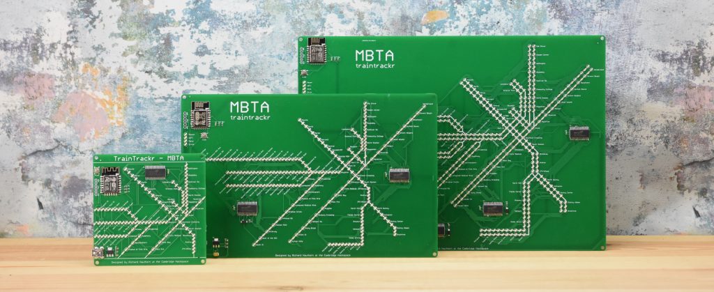
Some of our boards come with standard 0805 LEDs driven by the HT16K33 LED driver chip, to drive this you’ll need to use a suitable library.
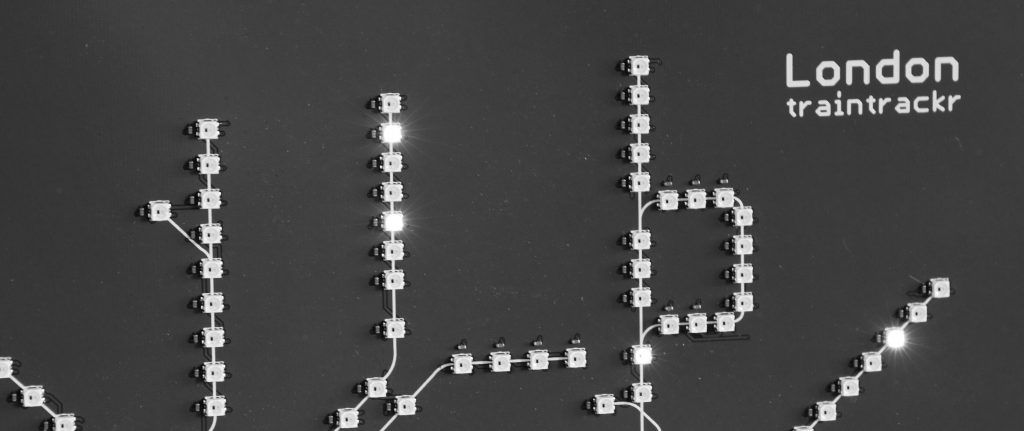
If you are trying to reprogram one of our boards with onboard RGB LEDs (WS2812-mini) you’ll need a library that can speak to those LEDs.
The hardware side of programming your board is easy, you can either use an FTDI programming cable, or on some of our board we’ve included a USB to UART chip (CP2104), so all you need (apart from your computer and the board itself) is the USB cable that came in the box. You’ll need to check the board you received from us to see if we have included a CP2104 chip.
Programming Steps
- Write your code in the Arduino IDE and make sure it compiles
- In the board manager select ESP8266
- Holding the onboard ‘Flash’ button, connect your board to your computer via USB
- Release the flash button
- Make sure you have the correct port selected, it will look something like SLAB_USBtoUART (if using the CP2104 chip)
- Upload to your board
We’ve put together a very simple Arduino sketch to get you started with the basics, it’s then up to you to write some code and make something amazing.
Schematics and basic firmware can be found here: https://github.com/Traintrackr/board_files
If you need to reset your board to it’s original firmware, you can find our instructions here
Let us know how you get on with your boards, we’d love to see what you do with them.